Preparing the Black Arrow GT3 Italia for GT Euroseries
by Tamar Nelwan. Images Matthew Tucker (Rockingham) & Richard August (South Manchester Slot Racing)
This car has a light and well detailed body with a fully tuneable chassis. By its performance the BA 458 GT3 has carved itself a good reputation in the analoge competitions where ever it ran.
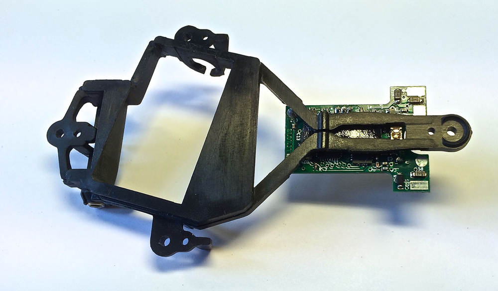
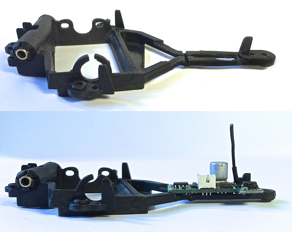
However the architecture of the fully sprung motorpod is a bit of a hindrance when it comes to fitting an O201b1 chip. There’s a central beam running from the motor to the front suspension point..which is exactly in the area where you would want to place it.
Installation with an IR lane change led on lead wires
To get the Lane change IR LED within the 35mm distance of the guide (as advised by Slot.it) it is necessary to mount a second IR LED via lead wires. This is achieved by drilling a hole between the front bodymount and the front suspension post.
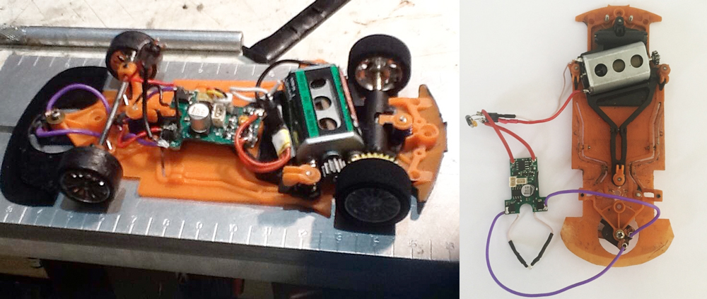
As you can see on the image below left, Matthew has made it into a neat and compact package with a minimum of wire length. At the motor side of the chip Matt placed a connector in the motor wires to facilitate and easy change of chip/ motor and or between analoge and digital running.
For a more detailed description of such a connector; check this post on SlotForum.
Richard has followed suit (see image below right) but still has some wire trimming to do. It looks like he kept quite a bit of the IR LED legs, nicely insulated with heat shrink I must point out, as the LED sits right under the (metal) front axle.
note: Slot.it has a set with an IR led and wires (SP32), Surechange guides also sells IR LED’s.
Height of IR LED above the track
If you use one of the 3mm IR LED’s best practice is to glue a 1mm thick round piece of plastic with a 4mm ø on top of the chassis. Drill the 3mmø hole through the plastic and chassis. This will give you more material to mount your IR LED in. Chamfer the bottom of the hole to 4mmø and mount the LED flush with or just above the chassis bottom.
I asked Maurizio Ferrari (Slot.it) once what the ideal height above the track would be and he could not give me an exact answer. The IR led has a conical beam, the lower you go the narrower the beam, meaning the shorter the time the led will shine on the LC sensor (less time for data transfer).
The higher you go the wider the beam (longer time for data transfer), but with the increase of distance the power of the beam will become weaker. Trail and error shows that its best to keep your IR led higher than the Chassis floor cause scratches on the led surface will definately disturb the IR beam.
Installation with the stock IR lane change led (needs to be tested)
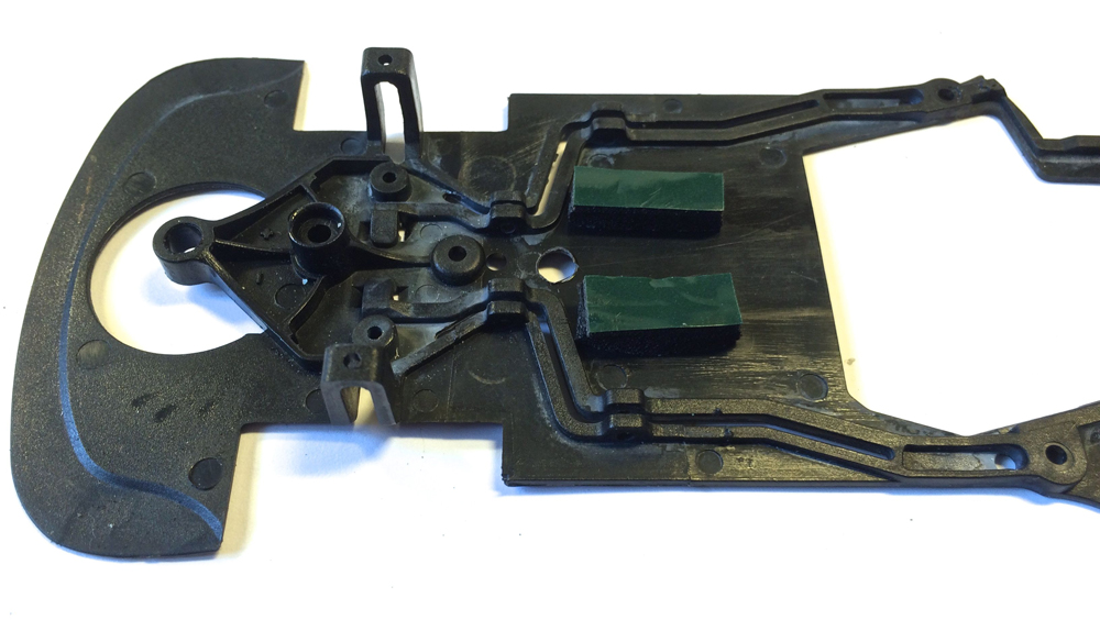
Having the lane change LED on leads placed well within the 35mm range is the option that will guarantee the best lane changes, but its not the only option. You could make do with the stock IR LED on the chip with just minor modifications to the F458 chassis.
Pictured below I’ve mounted the O2 chip in exactly the same position as Matt (just behind the front suspension mount) and drilled a hole in the chassis for the LED to shine trough.
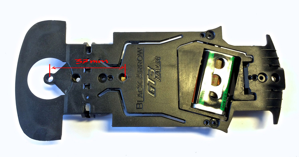
The distance between the LED and the guide is 37mm, just 2mm outside the advised range. If you shave 2mm of the suspension cup retainer tab you could move the chip even further forward and be be spot on.
To mount your chip as low as possible you can enlarge the slot in the pod beam so the IR led will fit within. You can also reduce the thickness of the pod beam to ount the chip even lower. If you do this its best to use some epoxy to glue the two halves of the beam together.
Mount the chip on top with some double sided foam tape and you’ll regain the rigidity of the beam.
Last but not least, if you add a second IR LED the one on the chip still functions, so there’s a 3rd option…use option 1 and 2 together!
To be or not to be (Chip mounted on the pod or on the chassis)
That is the question! And this is not a digital one, but a pure down to earth anologe chassis set-up question.
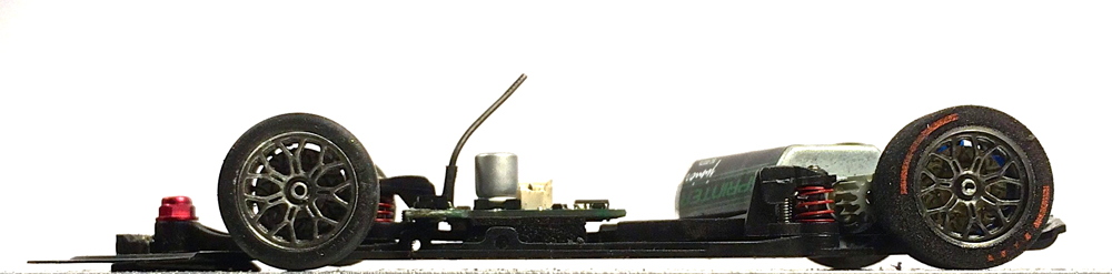
The O201b1 chip weights ≠ 3,5 gr (depending on the wires you use) so the question is; do you want that weight on the pod or on the chassis? If you were to choose for weight on the chassis here’s what you could do:
Fit two pieces of foam/ rubber/ plastic on either side of the pod beam to support the chip. Mount the chip on top with some double sided foam tape, making sure that there’s enough room for the pod to move freely under the chip.
With your chip now fixed to the chassis, check that your motor wires are flexible enough so they dont limit the pod movement.
All the mods decribed above are covered by DiSCA GT3 Euroseries regulation 2.2: Chassis modifications to aid fitment of digital chip and/or light kit are allowed
