Word and images By Tamar Nelwan
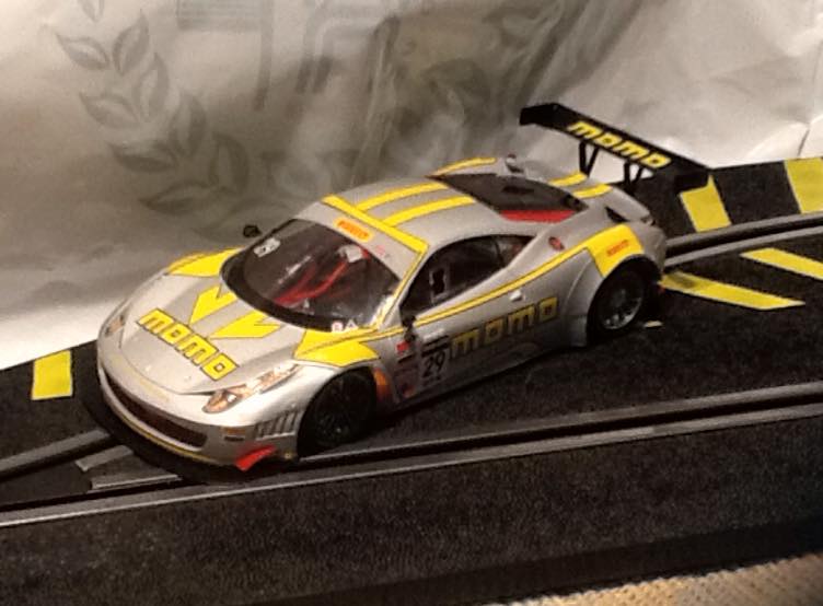
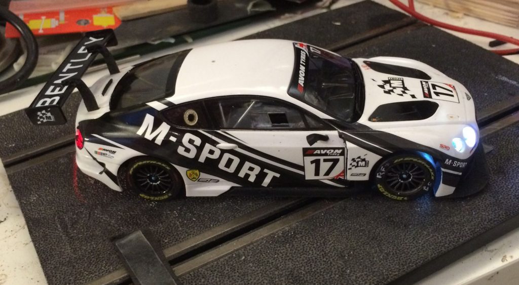
Here’s an article on preparing a GT3 car. My Scalextric Bentley Continental GT3 is equipped with a Slot.it 3Dfab chassis and a 0,0mm offset Evo 6 pod, and chipped with the Slot.it O201b1 digital chip.
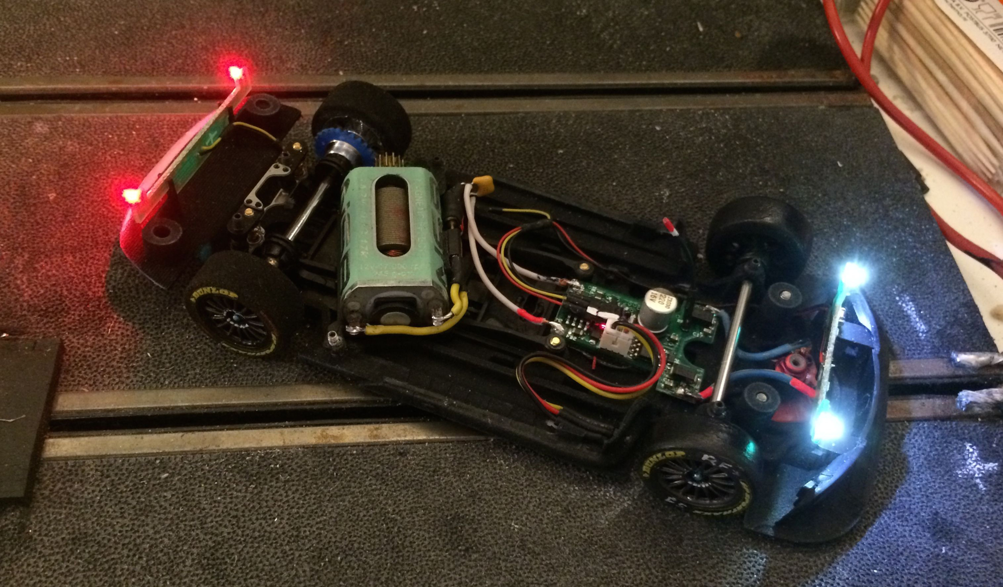
I have now been able to fit the car with functional headlights (as required by the rules) and brake lights without the use of an extra light set. In the case of the heavy Bentley this helps to keep the weight (and cost) down as well.
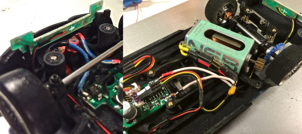
Slot.it has copied most of the Scalex chassis features on its 3DP chassis including the mounting brackets for the front and rear PCB boards with the SMD lights. All you need to do is to transplant the stock Scalex pcb boards form the Original chassis to the 3DP chassis and connect the wires to the O201b1 chip light socket. You can do this by using one of the Slot.it SP 34 lighting kit connectors.
Connect the + red wire of the front led board to the + red wire of the connector. Connect the + red wire of the rear led board to the yellow/orange wire of the connector.
Connect all – black wires together…et voila….You’ve got working front lights and brake lights.
Make sure that your guide wires clear the LED board with the guide turning .
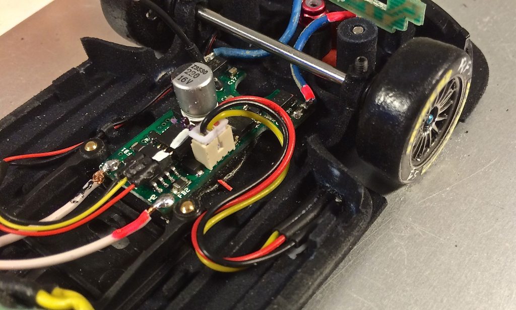
Now the stock wires are a bit big and the Slot.it connectors are not the most usere friendly if you want to mount and dismount them frequently. So I’ve swapped the wires for some smaller guage (modeltrain) wires and used PCB pin headers and sockets for the connectors.
For the lights I’ve used the smaller connectors (max 1amp CS 1,27 mm pin spacing) and soldered a socket directly to the chip at a 90˚ angle.
+ red is to the right pin, – black to the left pin + brake yellow/orange is on the middle pin.
O2 Chip and Hall Senor installation with a connector: swap between analoge and digital testing
Some racers might want to test their cars on analogue tracks. Although O2 facilitates analogue running, some clubs are not comfortable having a live open lane in the case another car finds it’s way onto it. Here’s a tip that will allow you to switch easilly between an analogue and digital setup.
As you can see in the picture (above right), I’ve mounted a PCB connector between the O2 chip and the Motor. Here I used a bigger connector (max 3,5amp CS 2 mm pin spacing) as you don’t want any loss of power.
Make a second set of lead wires and you can now easilly swap between an analoge and digital running.
Add some wheight to compensate for the chip and the hall sensor and your set up testing will remain consistent.
Note: If you do this conversion it is wise to solder the ferrite man on to the chip connector.
You need the little ferrite man for digital running but is been know to blow if left in place during analoge use. Also if you use these type of connectors, mark the correct mounting position. You would not be the first to leave the startline…backwards .
Here’s a usefull link to Conrad.UK for such connectors.
Hall sensor placement, make you laps count!
If on an analoge track you pass the start/finish line but the RMS does not count your lap most of you will address the Race direction.
..’cause clearly something must be wrong with the lap counter !!
In digital racing this is not always true…here the competitor shares resposibility to make all laps count by installing the Hall sensor correctly.
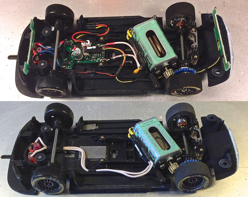
Make sure its mounted with the beveled side facing downwards, mount it at least @ 20mm offset to the slot and keep the cables clear from your motor and light cables. Last but not least, check the height of your Hall sensor above the track.
On a run of the mill Slot.it chassis this will not be an issue, but with some of the chassis in the GT3 class it can be (NSR and some 3DP chassis) as they have thicker chassis. In the case of the Slot.it 3DP chassis for the Bentley. Most likely the same will apply for the McLaren and F458. I’ve milled a small recess in the chassis to get the hall sensor closer to the track.
There’s a small bulkhead on the Bentley chassis right behind the front wheels, I’ve cut a hole here that I can push the Hall sensor through. Its a tight fit, so I don’t need to glue the sensor down. Again this makes it easier to swapp between analog and digital.